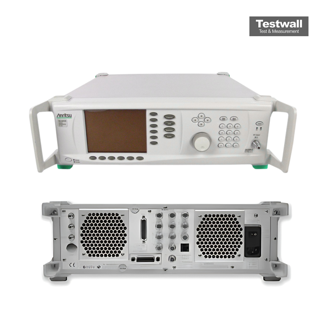
Anritsu MG3694B
| Attribut | Wert |
|---|---|
| Frequenzbereich | 2 MHz – 40 GHz |
| Ausgangsleistung (maximal) | +20 dBm |
| Ausgangsleistung (minimal) | -110 dBm |
| Frequenzauflösung | 1 Hz |
| Phasenrauschen (typisch) | -116 dBc/Hz bei 10 kHz Offset (bei 10 GHz) |
| Frequenzgenauigkeit | ± 1 ppm (intern Referenz) |
| Modulationsarten | AM, FM, PM, Pulsmodulation |
| Spektrale Reinheit (Oberwellen) | ≤ -55 dBc |
| Ausgangsanschluss | 2,92 mm (K-Typ), weiblich |
| Stromversorgung | 100–240 V AC, 50/60 Hz |
Anritsu MG3694B Options:
- MG3694B - 1A - Rack Mount with slides – Rack mount kit containing a set of track slides (90 degree tilt capability), mounting ears, and front panel handles to let the instrument be mounted in a standard 19-inch equipment rack.
- MG3694B - 1B - Rack Mount without slides – Modifies rack mounting hardware to install unit in a console that has mounting shelves. Includes mounting ears and front panel handles.
- MG3694B - 2A - Mechanical Step Attenuator – Adds a 10 dB/step attenuator. Rated RF output power is reduced.
- MG3694B - 2B - Mechanical Step Attenuator – Adds a 10 dB/step attenuator. Rated RF output power is reduced.
- MG3694B - 2C - Mechanical Step Attenuator – Adds a 10 dB/step attenuator. Rated RF output power is reduced.
- MG3694B - 3 - Ultra Low Phase Noise, main band – Adds new modules to significantly reduce SSB phase noise.
- MG3694B - 4 - 10 MHz to 2.2 GHz RF coverage, Ultra-Low Phase Noise version – Uses a digital down converter to significantly reduce SSB phase noise.
- MG3694B - 5 - 10 MHz to 2 GHz RF coverage – Uses an analog down converter.
- MG3694B - 6 - Analog Sweep Capability – (limited to ≥500 MHz when used with Option 4).
- MG3694B - 7 - IF Up-Conversion – Adds an internal 40 GHz mixer for up-converting an IF signal.
- MG3694B - 8 - Power Monitor – Adds internal power measurement capability. (Not available with Option 9.)
- MG3694B - 9K - Rear Panel Output – Moves the RF output connector to the rear panel.
- MG3694B - 9V - Rear Panel Output – Moves the RF output connector to the rear panel.
- MG3694B - 10 - User-Defined Modulation Waveform Software – External software package provides the ability to download user-defined waveforms into the memory of the internal waveform generator, serially or via GPIB.
- MG3694B - 12 - Frequency and Phase Modulation – External, via a rear panel BNC connector. For internal modulation capability, requires additionally LF Generator, Option 27.
- MG3694B - 14 - Amplitude Modulation – External, via a rear panel BNC connector. For internal modulation capability, requires additionally LF Generator, Option 27.
- MG3694B - 15A - High Power – Adds high-power RF components to the instrument to increase its output power level.
- MG3694B - 15B - High Power – Adds high-power RF components to the instrument to increase its output power level.
- MG3694B - 15C - High Power – Adds high-power RF components to the instrument to increase its output power level.
- MG3694B - 16 - High Stability Time Base – Adds an ovenized, 10 MHz crystal oscillator as a high-stability time base.
- MG3694B - 17 - Delete Front Panel – Deletes the front panel for use in remote control applications where a front panel display and keyboard control are not needed. (Only available with Options 1A or 1B)
- MG3694B - 18 - mmW Bias Output – Adds a rear panel BNC Twinax connector required to bias the 63850 series millimeter wave source modules, sold separately. Includes DC bias cable.
- MG3694B - 22 - 0.1 Hz to 10 MHz Audio coverage – Uses a DDS for coverage down to approximately DC. Output power is derated by 2 dB. Frequency resolution below 10 MHz is 0.02 Hz. No modulation available in the 0.1 Hz to 10 MHz band.
- MG3694B - 26B - Pulse Modulation – External, via a rear panel BNC connector. For internal modulation capability, requires additionally Pulse Generator, Option 27.
- MG3694B - 27 - Internal LF and Pulse Generators – Provides modulation waveforms for internal AM, FM, ΦM, and Pulse. (Not available without Option 12, 14, or 26.)
- MG3694B - 28B - Analog Modulation Suite – Bundles Options 12, 14, 26B and 27, offering internal and external AM, FM, ΦM, and Pulse Modulation.
- MG3694B - 30 - Low Phase Noise. (Not available with Option 3.)
- MG3694B - 98 - Standard calibration to ISO 17025 and ANSI/NCSL Z540.
- MG3694B - 99 - Premium calibration to ISO 17025 and ANSI/NCSL Z540. Test report and uncertainty data included.
| Model | MG3694B |
|---|
Der Anritsu MG3694B RF/Mikrowellensignal-Generator deckt den Frequenzbereich von 2–40 GHz mit einer Auflösung von 0,01 Hz ab und synchronisiert die Zeitbasis präzise mit interner oder externer 10‑MHz-Referenz. Er liefert bis zu +23 dBm bei 40 GHz, Phasenrauschen von –94 dBc/Hz bei 1 kHz Offset und einen schnellen Umschaltzeitpunkt von etwa 5 ms pro Punkt. Optional sind ein analoges Rampen-Sweep und externe 10‑MHz-Referenzein-/ausgänge verfügbar.
Ingenieure in Forschung & Entwicklung, Fertigung und Reparatur schätzen den Anritsu MG3694B für Filter-, Verstärker- und Komponentenprüfung dank konstanter Ausgangsleistung, hoher spektraler Reinheit und robuster Zuverlässigkeit.
Testwall kann den gebrauchten Anritsu MG3694B liefern, vollständig getestet. Mit fachkundigem Support und weltweitem Versand stellt Testwall Hochleistungsgeräte bereit – mit unvergleichlicher Zuverlässigkeit und Servicequalität. Bitte kontaktieren Sie uns direkt, wenn Sie Kalibrierung oder Reparatur des Anritsu MG3694B wünschen.