emtest
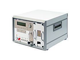
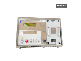
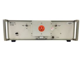
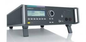
emtest UCS200N
Automotive Transient Tester
200 V (Spitze) Ausgangsspannung
DC, 50 Hz, 60 Hz, 400 Hz Frequenzbereich
ISO 7637-2, ISO 16750-2, DIN 40839 Prüfnormen
5 integrierte Impulsgeneratoren (Pulse 1, 2a, 2b, 3a, 3b) Anzahl der Impulsgeneratoren
200 A (Spitzenwert) Maximaler Ausgangsstrom
| Attribut | Wert |
|---|---|
| Ausgangsspannung | 200 V (Spitze) |
| Frequenzbereich | DC, 50 Hz, 60 Hz, 400 Hz |
| Prüfnormen | ISO 7637-2, ISO 16750-2, DIN 40839 |
| Anzahl der Impulsgeneratoren | 5 integrierte Impulsgeneratoren (Pulse 1, 2a, 2b, 3a, 3b) |
| Maximaler Ausgangsstrom | 200 A (Spitzenwert) |
| Versorgungsspannung | 230 V AC, 50/60 Hz |
| Betriebstemperaturbereich | 0 °C bis +40 °C |
| Schnittstellen | USB, RS-232, IEEE 488 (GPIB) |
| Steuerung | Integriertes Touchscreen-Display sowie PC-Steuerung über Software |
| Abmessungen (B x H x T) | 483 mm x 177 mm x 500 mm (19 Zoll Rackmontage, 4 HE) |
emtest UCS200N Options:
- UCS200N - UCS200N50 - Built-in coupling/decoupling network, 80V/50A, 100A@500ms
- UCS200N - UCS200N100 - Built-in coupling/decoupling network, 80V/100A, 150A@500ms
- UCS200N - UCS200N150 - Built-in coupling/decoupling network, 80V/150A
- UCS200N - UCS200N200 - Built-in coupling/decoupling network, 80V/200A
- UCS200N - ACC - Capacitive coupling clamp
- UCS200N - KW50 - 100:1 divider, 50ohm
- UCS200N - KW1000 - 500:1 divider, 1,000ohm
- UCS200N - CA EFT KIT - EFT/Burst verification kit
- UCS200N - A6dB - 6dB attenuator, 50ohm
- UCS200N - CA ISO - Load resistors for the verification of micropulses and Load Dump pulses
- UCS200N - iso.control - Software to control the test, including standard library, test report facility and data conversion generator
| Model | UCS200N |
|---|
EMTEST UCS200N / EM Test UCS 200NThe EM Test UCS 200N Ultra-Compact Simulator for Automotive Transients unifies the capabilites of an EFT/Burst simualtor, a Micropulse simulator and the required coupling network into one box. The UCS 200N Transient Tester is equiped to meet all international and car manufacturer specifications from around the globe. The built-in coupling network ranges from 50A, up to 200A depending on the model / option specified. The built-in coupling network can be used and controlled by any unit of the LD 200N, VDS 200N and PFS 200N. For tests beyond standard's requirements the waveform parameters of the Micropulse generator can be varied in a wide range by means of the FreeStyle mode.The EM Test UCS200N has the following specifications:UCS 200N MODELS UCS 200N50 Built-in coupling/decoupling network, 80V/50A, 100A@500ms UCS 200N100 Built-in coupling/decoupling network, 80V/100A, 150A@500ms UCS 200N150 Built-in coupling/decoupling network, 80V/150A UCS 200N200 Built-in coupling/decoupling network, 80V/200A INPUT: DUT supply +/-: DC voltage from VDS 200N or any other DC supply Pulse 5, 7: From one LD 200N OUTPUT: DUT supply +/-: Central DUT output Coaxial output port: To connect the capacitive coupling clamp as per ISO 7637-3:2007 ELECTRICAL FAST TRANSIENTS EFT/BURST MODULE FOR TEST PULSES 3A/3B As per ISO 7637-2 Test voltage: 25V - 1,000V ± 10% Rise time: 5ns ± 1.5ns Pulse duration: 150ns ± 45ns Verification: As per Annex C of ISO 7637-2:2011 into 50ohm and 1,000ohm load Source impedance: Zq = 50ohm Polarity: Positive/negative (Pulse 3b/3a) TRIGGER CIRCUIT Trigger of bursts Automatic: manual, external Burst duration: T4 = 0.1ms - 999.9ms Repetition rate: T5 = 10ms - 9,999ms Spike frequency: f = 0.1kHz - 200kHz Test duration: T = 0:01min - 999:59min, T > 999:59min --> endless OUTPUTS Direct: Via 50ohm-coaxial connector (for tests using e.g. a capacitive coupling clamp) Coupling mode: To the + battery line (supply lines) CRO trigger: 5V trigger signal for Oscilloscope TEST ROUTINES Quick Start: On-line adjustable parameters, easy-to-use Standard Test Routines: As per ISO 7637-2:2011, Levels 1 - 4 User Test Routines: Random burst release. Change voltage after T. Change frequency after T MICROPULSES MICROPULSE MODULE FOR TEST PULSES 1, 2A AND 6: As per ISO 7637-2:2011 Test voltage: U = 20V - 600V ± 10% (peak voltage and polarity as per selected standard) Repetition rate: 0.2s - 99.0s ISO PULSE 1 (12V) Rise time: 1us +0%/-50% (10% - 90%) Pulse duration: 2ms ± 10% (10% - 10%) Int. resistor: 10ohm ± 10% ISO PULSE 1 (24V) Rise time: 3us +0%/-50% (10% - 90%) Pulse duration: 1ms ± 10 (10% - 10%) Int. resistor: 50ohm ± 10% ISO PULSE 2 (12V/24V) Rise time: 1us +0%/-50% (10% - 90%) Pulse duration: 50us ± 10% (10% - 10%) Int. resistor: 2ohm ± 10% ISO PULSE 6 (12V) AS PER ISO 7637-1:1990 Rise time: 60us +0%/-50% (10% - 90%) Pulse duration: 300us ± 10% (10% - 10%) Int. resistor: 30ohm ± 10% AS PER ISO 7637-2 THE FOLLOWING STANDARDS CAN BE COVERED SAE J1113 GM 3097 BMW Volkswagen PSA Chrysler PF 9326 DC 10614 Renault FIAT Mitsubishi Honda Ford ES-XW7T TRIGGER Automatic: Automatic release of the pulses Manual: Manual release of a single pulse External: External release of a single pulse Battery switch: Off time, selectable; 0 - 10,000ms OUTPUT DUT supply +/-: Central DUT output Coupling: To the battery +line Decoupling: Via diode and battery supply switch TEST ROUTINES Quick Start: Immediate start; easy to use and fast User Test Routines: 1. Custom made test routines and 2. Change voltage after n pulses Standard Test Routines: As per ISO 7637, SAE J1113, JASO and manufacturer specifications Service: Service, setup, self test